REV. A
36
ADM1027
ENHANCING SYSTEM ACOUSTICS
Automatic fan speed control mode reacts instantaneously to
changes in temperature, i.e., the PWM duty cycle will respond
immediately to temperature change. Any impulses in tempera-
ture can cause an impulse in fan noise. For psycho-acoustic
reasons, the ADM1027 can prevent the PWM output from
reacting instantaneously to temperature changes. Enhanced
acoustic mode will control the maximum change in PWM duty
cycle in a given time. The objective is to prevent the fan cycling
up and down and annoying the system user.
Acoustic Enhancement Mode Overview
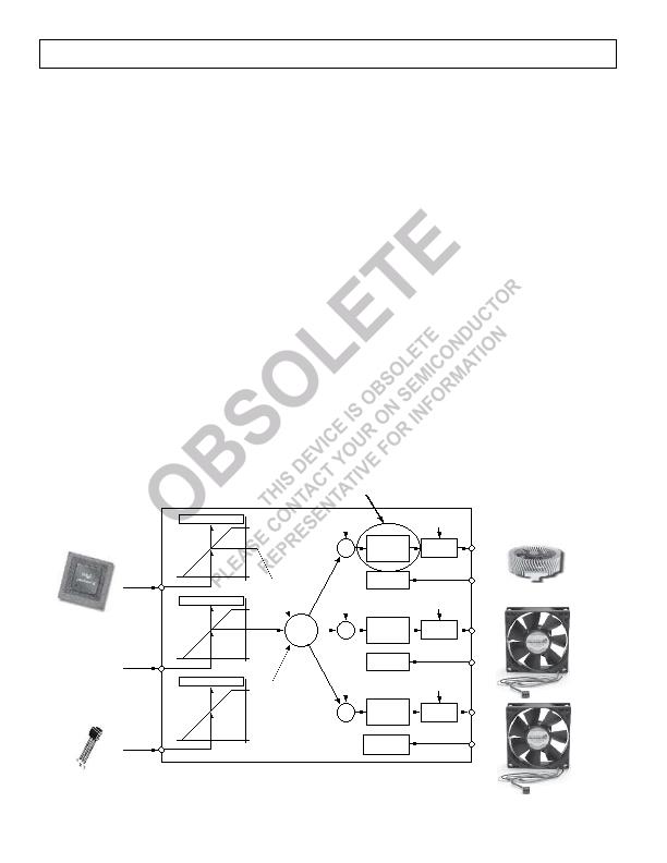
Figure 37 gives a top-level overview of the automatic fan
control circuitry on the ADM1027 and where acoustic
enhancement fits in. Acoustic enhancement is intended as a
post-design tweak when a system or mechanical engineer is
evaluating best settings for the system. Having determined the
optimal settings for the thermal solution, the engineer can adjust
the system acoustics. The goal is to implement a system that is
acoustically pleasing without causing the user annoyance due to
fan cycling. It is important to realize that although a system may
pass an acoustic noise requirement specification, e.g., 36 dB,
if the fan is annoying, it will fail the consumer test.
The Approach
There are two different approaches to implementing system
acoustic enhancement. The first method is temperature-centric.
This involves smoothing transient temperatures as they are mea-
sured by a temperature source, e.g., Remote 1 temperature.
The temperature values used to calculate PWM duty cycle
values would be smoothed, reducing fan speed variation. However,
this approach causes an inherent delay in updating fan speed
and causes the thermal characteristics of the system to change.
It also causes the system fans to stay on longer than necessary,
since the fan reaction is merely delayed. The user also has no
control over noise from different fans driven by the same tempera-
ture source. Consider controlling a CPU cooler fan (on PWM1)
and a chassis fan (on PWM2) using Remote 1 temperature.
Because the Remote 1 temperature is smoothed, both fans will
be updated at exactly the same rate. If the chassis fan is much
louder than the CPU fan, there is no way to improve its acoustics
without changing the thermal solution of the CPU cooling fan.
The second approach is fan-centric. The idea is to control the
PWM duty cycle driving the fan at a fixed rate, e.g., 6%. Each
time the PWM duty cycle is updated, it is incremented by a
fixed 6%. So the fan ramps smoothly to its newly calculated
speed. If the temperature starts to drop, the PWM duty cycle
immediately decreases by 6% every update. So the fan ramps
smoothly up or down without inherent system delay. Consider
controlling the same CPU cooler fan (on PWM1) and chassis
fan (on PWM2) using Remote 1 temperature. The T
MIN
and
T
RANGE
settings have already been defined in automatic fan
speed control mode, i.e., thermal characterization of the control
loop has been optimized. Now the chassis fan is noisier than the
CPU cooling fan. So PWM2 can be placed into acoustic
enhancement mode independent of PWM1. The acoustics of
the chassis fan can therefore be adjusted without affecting the
acoustic behavior of the CPU cooling fan, even though both
fans are being controlled by Remote 1 temperature. This is
exactly how acoustic enhancement works on the ADM1027.
ACOUSTIC
ENHANCEMENT
TACHOMETER 1
MEASUREMENT
RAMP
CONTROL
(ACOUSTIC
ENHANCEMENT)
TACHOMETER 2
MEASUREMENT
RAMP
CONTROL
(ACOUSTIC
ENHANCEMENT)
TACHOMETERS 3
AND 4
MEASUREMENT
PWM
GENERATOR
PWM
GENERATOR
RAMP
CONTROL
(ACOUSTIC
ENHANCEMENT)
PWM
GENERATOR
PWM
CONFIG
PWM
MIN
MUX
THERMAL CALIBRATION
100%
0%
T
MIN
T
RANGE
THERMAL CALIBRATION
100%
0%
T
MIN
TRANGE
THERMAL CALIBRATION
100%
0%
T
MIN
T
RANGE
PWM
MIN
PWM
MIN
PWM
CONFIG
PWM
CONFIG
REMOTE 1 =
AMBIENT TEMP
LOCAL =
VRM TEMP
REMOTE 2 =
CPU TEMP
PWM1
TACH1
CPU
FANSINK
FRONT
CHASSIS
REAR
CHASSIS
PWM3
TACH3
PWM2
TACH2
Figure 37. Acoustic Enhancement Smooths Fan Speed Variations Under Automatic Fan Speed Control
Rev. 3 | Page 36 of 56 | www.onsemi.com
发布紧急采购,3分钟左右您将得到回复。
相关PDF资料
ADM1029ARQZ-R7
IC SENSOR 2TEMP/FAN CTRL 24QSOP
ADM1030ARQZ-RL7
IC SNSR TEMP/FAN PWM CTRL 16QSOP
ADM1032ARZ-REEL
IC TEMP MONITOR 85DEG 8SOIC
ADM1033ARQZ-RL7
IC THERM/FAN SPEED CTLR 16-QSOP
ADM1034ARQZ-REEL
IC THERM/FAN SPEED CTRLR 16-QSOP
ADN8810ACPZ-REEL7
IC CURRENT SOURCE(12BIT) 24LFCSP
ADP2140ACPZ3328R7
IC REG DL BCK/LINEAR 10LFCSP
ADP5022ACBZ-6-R7
IC REG TRPL BCK/LINEAR 16WLCSP
相关代理商/技术参数
ADM1027ARQZ-RL71
制造商:ONSEMI 制造商全称:ON Semiconductor 功能描述:dBCOOLa?¢ Remote Thermal Controller and Voltage Monitor
ADM1028
制造商:AD 制造商全称:Analog Devices 功能描述:Remote Thermal Diode Monitor with Linear Fan Control
ADM1028ARQ
功能描述:IC SENSOR TEMP/FAN CTRL 16QSOP RoHS:否 类别:集成电路 (IC) >> PMIC - 热管理 系列:- 标准包装:1 系列:- 功能:温度监控系统(传感器) 传感器类型:内部和外部 感应温度:-40°C ~ 125°C,外部传感器 精确度:±2.5°C 本地(最大值),±5°C 远程(最大值) 拓扑:ADC,比较器,寄存器库 输出类型:2 线 SMBus? 输出警报:无 输出风扇:无 电源电压:2.7 V ~ 5.5 V 工作温度:-40°C ~ 125°C 安装类型:表面贴装 封装/外壳:SOT-23-8 供应商设备封装:SOT-23-8 包装:Digi-Reel® 其它名称:296-22675-6
ADM1028ARQ-REEL7
制造商:Rochester Electronics LLC 功能描述:TDM + LINEAR FAN CONTROL I.C. - Tape and Reel
ADM1029
制造商:AD 制造商全称:Analog Devices 功能描述:Dual PWM Fan Controller and Temperature Monitor for High Availability Systems
ADM1029ARQ
制造商:Rochester Electronics LLC 功能描述:TDM AND FAN CONTROLLER I.C. - Bulk
ADM1029ARQ-REEL7
制造商:Rochester Electronics LLC 功能描述: 制造商:Analog Devices 功能描述:
ADM1029ARQZ
功能描述:马达/运动/点火控制器和驱动器 +/- 1 C Digital Serial RoHS:否 制造商:STMicroelectronics 产品:Stepper Motor Controllers / Drivers 类型:2 Phase Stepper Motor Driver 工作电源电压:8 V to 45 V 电源电流:0.5 mA 工作温度:- 25 C to + 125 C 安装风格:SMD/SMT 封装 / 箱体:HTSSOP-28 封装:Tube